
Read ArticleRead ArticleDiscussion - Method 1: Examining Element Description The element description provides...
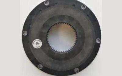
Explore practical KTR BoWex-ELASTIC coupling guides for engineers, maintenance teams, equipment owners and spare-parts buyers. This technical knowledge section explains how to identify an installed BoWex-ELASTIC coupling element, interpret its description, determine the correct size, check the HE execution and confirm the required Shore hardness.
BoWex-ELASTIC is a highly flexible flange coupling system used in demanding engine-driven applications. The coupling combines an elastic ring-shaped element with an axially inserted BoWex hub. Correct replacement selection requires more than matching the general shape or outside diameter.
The articles in this category focus on practical identification, inspection and replacement questions. Use them to collect the correct technical information before ordering and to avoid selecting an element with the wrong size, mounting execution, SAE connection or elastomer hardness.
KTR BoWex-ELASTIC is a highly flexible flange coupling designed to transfer torque while damping torsional vibration, reducing shock loads and limiting structure-borne noise.
The coupling normally consists of:
The plug-in construction allows the internal BoWex hub to engage axially with the elastic element. The complete assembly can accommodate drivetrain displacement within the limits specified for the selected coupling type.
BoWex-ELASTIC couplings are available in different sizes, elastomer hardnesses, HE designs and engine-side flange dimensions. These variants should not be treated as interchangeable simply because their general construction appears similar.
Correct identification should begin with the complete description visible on the installed elastic element. Inspect the front, rear and complete circumference because dirt, paint, oil or the mounting position can conceal part of the marking.
Use the KTR BoWex Elastic identification guide to understand which markings, dimensions and photographs should be collected.
Look for information such as:
Copy the complete description exactly as it appears. Do not omit letters, numbers, fractions or the Shore hardness because each part can be relevant to identifying the correct replacement.
A typical element description may appear in a format similar to:
BoWex-ELASTIC 48 HE 6 1/2
The individual sections provide different identification information:
More detailed product descriptions may also specify the HE1/HE2 or HE3/HE4 execution, actual flange diameter and Shore hardness.
For example, a listing such as BoWex Elastic 48 HE1/HE2 Ø215.8 SAE6.5 Shore 50 contains significantly more selection information than the general description “BoWex Elastic 48”.
Before requesting a replacement BoWex-ELASTIC element, collect all available information from the existing coupling and the complete machine.
Please provide:
The full product description should be used as the primary identification reference whenever it remains readable. Dimensions, photographs and machine information should provide additional confirmation.
The current AWELASTIC range includes original BoWex-ELASTIC elements in five principal nominal sizes:
The nominal size is only one part of the selection. Elements within the same size can differ by HE execution, outside diameter, SAE connection and Shore hardness.
BoWex-ELASTIC 42 is used in relatively compact engine-driven applications. The AWELASTIC range includes HE1/HE2 elements with different flange dimensions and Shore hardness options.
When identifying a size 42 element, verify:
A BoWex-ELASTIC 42 element with one flange diameter should not automatically be replaced by another size 42 version.
BoWex-ELASTIC 48 is available in several configurations. Current products include HE1/HE2 and HE3/HE4 executions with standard or SAE-related flange dimensions.
Examples include elements described with:
This illustrates why the words “BoWex Elastic 48” alone are insufficient for ordering. The complete HE design, diameter, SAE size and Shore value must be checked.
BoWex-ELASTIC 65 elements are used in larger engine-driven power-transmission systems. AWELASTIC listings include HE1/HE2 and HE3/HE4 versions with different flange connections.
Examples represented in the catalogue include:
The SAE10 and SAE11.5 elements are separate products and should not be considered interchangeable because they share the same nominal size.
BoWex-ELASTIC 80 is intended for higher-capacity drivetrain configurations. Available versions can differ by outside diameter, SAE flywheel connection and elastomer hardness.
Current product configurations include HE1/HE2 elements with standard and SAE11.5-related flange dimensions.
Before ordering, verify the complete product code, flange diameter, Shore hardness and matching hub specification.
BoWex-ELASTIC 100 is used in selected higher-power engine-driven applications. The larger nominal size does not remove the need to verify the complete mounting and drivetrain specification.
Check:
A size 100 element should be selected from the complete technical description rather than nominal size alone.
BoWex-ELASTIC elements are manufactured in different HE executions. HE1, HE2, HE3 and HE4 identify different coupling configurations and axial arrangements.
Although two products may use the same nominal rubber element size, the complete coupling arrangement and connected hub can differ.
Before selecting an HE type, verify:
Do not substitute HE1/HE2 and HE3/HE4 versions solely because they share the same element size or Shore hardness.
Many BoWex-ELASTIC flange elements are designed for engine-side connections corresponding with SAE J620 flywheel dimensions.
Product descriptions may include SAE references such as:
The applicable SAE sizes depend on the nominal BoWex-ELASTIC size and HE execution.
Before selecting an SAE element, confirm:
Do not identify an SAE connection from one approximate dimension. Compare the complete mounting pattern and original product description.
Not every BoWex-ELASTIC element is identified only by an SAE designation. Some products use special or application-specific outside flange dimensions.
When no SAE number is visible, accurately measure:
A photograph with measurement points clearly marked can help distinguish between visually similar elements.
The Shore A value describes the hardness of the BoWex-ELASTIC rubber element and influences the torsional stiffness and vibration behaviour of the complete drivetrain.
The current AWELASTIC catalogue groups products under:
Elements with identical outside dimensions can have different Shore hardness values and should not automatically be treated as interchangeable.
The correct Shore hardness is normally determined by the original coupling specification and the torsional requirements of the engine and driven equipment.
A lower Shore A value generally represents a softer and more torsionally flexible element, while a higher value represents a stiffer elastomer execution.
Changing the hardness can alter:
Do not select T40, T50 or T65 only according to availability or price. Retain the original value unless a different hardness has been technically confirmed for the complete drivetrain.
The internal teeth of the BoWex-ELASTIC element engage with the externally toothed BoWex hub. When the original description is unreadable, the tooth arrangement can provide valuable identification information.
Record:
The internal tooth count can help identify the probable coupling size, but it does not confirm the complete flange diameter, HE execution or Shore hardness.
The elastic flange element and the BoWex hub form a matched drive connection. A correctly identified rubber element can still be unsuitable when the existing hub belongs to another size or execution.
Inspect the hub for:
A new elastic element should not be installed over a severely worn or incorrectly sized hub.
BoWex-ELASTIC couplings are used in engine-driven systems exposed to torsional vibration and changing loads.
Typical applications can include connections between a diesel engine and:
The application type or machine model can help narrow the search, but it does not replace the original coupling designation. Similar machines may use different engines, flywheels, hubs or Shore hardness values.
An original KTR BoWex-ELASTIC element is manufactured for the defined dimensions, material characteristics, tooth geometry and torsional behaviour of the corresponding coupling system.
A visually similar alternative may differ in:
These differences can affect fitment, vibration behaviour and the service life of the complete engine-driven system.
When inspecting an existing or replacement element, look for:
A logo or similar external appearance alone does not confirm that an element is the correct original replacement for the installed drivetrain.
Inspect the coupling when the machine develops increased vibration, unusual drivetrain noise, irregular torque transmission or visible movement within the assembly.
Possible signs of wear or damage include:
The reason for premature failure should be investigated before installing a new element. Repeated damage can indicate worn hubs, incorrect axial positioning, loose mountings, unsuitable Shore hardness or another drivetrain problem.
Do not inspect only the visibly damaged rubber element. Check the complete engine-to-machine connection.
Inspect:
A new element can be damaged prematurely when installed with a worn hub, damaged flywheel connection, loose machine mounting or incorrect axial position.
Installation should follow the correct KTR assembly instructions for the specific element size and HE execution.
Before returning the equipment to service:
The coupling can compensate for specified drivetrain displacement, but it should not be used to correct major assembly errors, damaged supports or unsuitable engine-to-machine geometry.
Browse the complete range of original KTR BoWex Elastic coupling elements by nominal size, HE design, flange diameter and Shore hardness.
Individual product pages provide the complete product description, dimensions, photographs, stock information and ordering options.
The WooCommerce product category is intended for comparing and purchasing actual components, while this post category provides technical explanations, identification guidance and maintenance information.
Return to the complete KTR coupling catalogue to browse BoWex FLE-PA flanges, BoWex-ELASTIC elements, ROTEX spiders, BoWex M sleeves and related original components.
Each KTR coupling family has its own construction, identification method and intended application. BoWex-ELASTIC elements should not be confused with torsionally stiff BoWex FLE-PA flanges or BoWex M polyamide sleeves.
If the installed BoWex-ELASTIC element cannot be identified, send AWELASTIC the complete visible description, Shore hardness, measurements, internal tooth count, machine information and clear photographs.
The guides in this post category provide practical help with BoWex-ELASTIC size identification, HE type recognition, SAE flange selection, Shore hardness verification, wear inspection and original replacement element selection.
Read ArticleRead ArticleDiscussion - Method 1: Examining Element Description The element description provides...
Looks like you haven't made a choice yet.