
Read ArticleRead ArticleDiscussion - When your engine-to-pump connection fails, the coupling is often the first...

Explore practical KTR BoWex FLE-PA flange coupling guides for engineers, maintenance teams, machinery owners and spare-parts buyers. This technical knowledge section explains how to identify an installed BoWex FLE-PA flange, determine its size, count the internal teeth, check the SAE flywheel connection and select the correct matching hub.
BoWex FLE-PA couplings are used primarily between diesel engines and hydraulic pumps. Correct replacement selection requires more than matching the general colour, shape or outside diameter of the existing flange.
Flanges from the same product family can differ by nominal size, outside diameter, bolt pattern, SAE connection, internal tooth profile, mounting length and matching hub specification. The complete marking and drivetrain configuration should therefore be verified before ordering.
KTR BoWex FLE-PA is a torsionally stiff curved-tooth flange coupling designed for compact engine-to-pump drive connections.
The coupling normally consists of:
The polyamide and steel material combination allows the toothed connection to operate without regular lubrication. The compact design is particularly suitable for mobile machinery, hydraulic power units and other diesel-driven systems where installation space is limited.
The complete coupling can compensate for limited axial, radial and angular displacement within the values specified for the selected size and installation.
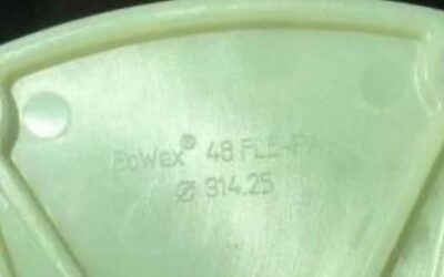
The most reliable identification method is to read the complete description printed, moulded or stamped on the installed flange.
Start with the KTR BoWex FLE-PA flange identification guide to see which markings, measurements and photographs should be collected.
Inspect the complete circumference and both sides of the flange. Dirt, paint, oil, corrosion or the installed position can conceal part of the description.
Typical markings can include:
Copy the complete description exactly as it appears. Do not omit hyphens, decimal values, diameter symbols or other numbers because each part can be relevant to the replacement.
A typical flange description can follow this structure:
BoWex 80 FLE-PA Ø314.25
The individual sections provide different identification information:
An outside diameter of approximately 314.25 mm is commonly associated with an SAE 10 flywheel connection. However, the complete bolt pattern, pilot dimensions and original marking should still be verified.
A description containing only “BoWex FLE-PA” is not sufficient because several sizes and flange diameters are available.
Before requesting a replacement BoWex FLE-PA flange, collect all available information from the existing coupling and the complete machine.
Please provide:
The original description should be used as the main identification reference whenever it remains readable. Measurements, tooth count and machinery information provide additional confirmation.
The current AWELASTIC product catalogue includes original BoWex FLE-PA flanges in the following principal sizes:
The identification documentation can also refer to additional BoWex FLE-PA sizes used in particular installations. The nominal size should always be checked from the original component rather than assumed from the machine model.
BoWex 48 FLE-PA is commonly used in compact diesel-engine and hydraulic-pump drive connections. AWELASTIC offers this size with multiple outside diameters, bolt patterns and flywheel connections.
Available flange diameters can range from compact application-specific versions to larger SAE-related flanges. This means that “BoWex 48 FLE-PA” alone is not a complete ordering description.
When identifying a size 48 flange, verify:
BoWex 48 FLE-PA flanges commonly use 50 internal teeth, but the complete flange dimensions must still be verified.
BoWex 65 FLE-PA is used in larger engine-to-pump drive systems and is available with both standardised and application-specific flange dimensions.
Examples include compact special-purpose flanges and larger versions designed around SAE flywheel dimensions.
When identifying a size 65 flange, verify:
BoWex 65 FLE-PA flanges commonly use 42 internal teeth. Tooth count alone does not identify the outside flange execution.
BoWex 80 FLE-PA is used in medium- and higher-capacity diesel-hydraulic drive systems.
A commonly encountered version has an outside diameter of approximately 314.25 mm corresponding with an SAE 10 flywheel connection. Other flange executions may also be available.
BoWex 80 FLE-PA flanges commonly use 46 internal teeth.
Before ordering, compare:
BoWex 100 FLE-PA is intended for higher-load engine-to-pump drive connections. Current AWELASTIC products include different outside flange diameters and SAE-related executions.
BoWex 100 FLE-PA flanges commonly use 48 internal teeth.
When identifying this size, verify:
A size 100 flange should not be selected only because it has the same internal tooth count as another BoWex size.
BoWex 125 FLE-PA is used in selected large engine-driven hydraulic and industrial applications.
The nominal size does not provide enough information to select the replacement. Check the complete product marking, outside diameter, bolt pattern, SAE connection and matching hub.
AWELASTIC product information currently contains inconsistent references to the number of internal teeth for some size 125 listings. For that reason, this guide does not state one universal tooth count for every BoWex 125 FLE-PA version.
Use the original flange description, hub marking, technical drawing and measured tooth count together when confirming a size 125 replacement.
When the flange description is worn or unreadable, the number of internal teeth can help identify the probable nominal size.
Common identification references include:
The tooth count is only one part of the identification. Flanges with different nominal sizes or outside dimensions can have tooth counts that appear similar.
Always combine the tooth count with:
Many BoWex FLE-PA flanges are designed for engine flywheels corresponding with SAE standards.
Depending on the coupling size and flange version, product descriptions can refer to SAE connections such as:
Before identifying a flange as an SAE version, confirm:
Do not determine the SAE size from one approximate diameter alone. Compare the complete dimensional pattern with the appropriate technical documentation.
Not every BoWex FLE-PA flange uses a standard SAE flywheel connection. AWELASTIC also supplies application-specific flanges with special diameters, bolt patterns and centring arrangements.
For a special flange, record:
A photograph showing the exact measurement points can help distinguish between similar special-purpose flanges.
The FLE-PA flange engages with a matching steel BoWex hub featuring external curved teeth. Correctly identifying the flange does not automatically confirm the correct hub.
Use the KTR BoWex hub identification guide when the hub part number is unavailable or difficult to read.
Hub selection can depend on:
The flange and hub must belong to the same compatible BoWex size and tooth system.
A damaged polyamide flange should not be replaced without inspecting the matching steel hub.
Check the hub for:
A new FLE-PA flange installed on a severely worn or incorrectly positioned hub can fail prematurely.
BoWex FLE-PA couplings can be installed in different axial arrangements depending on the hub design and available installation space.
When replacing the coupling, verify:
A hub installed in the wrong orientation or axial position can produce incomplete tooth engagement and premature wear.
BoWex FLE-PA flange damage is not always caused by normal material ageing. Failures can also result from an incorrect coupling selection or a problem elsewhere in the engine-to-pump connection.
Read the BoWex FLE-PA failure causes guide for a more detailed inspection checklist.
Common causes can include:
The underlying cause should be identified before installing a replacement flange.
Inspect the coupling when the machine develops unusual drivetrain noise, increased vibration, irregular hydraulic operation or visible movement between the engine and pump.
Possible signs of damage include:
Repeated flange damage can indicate that the hub, pump shaft, mounting arrangement or machine supports also require repair.
An original KTR BoWex FLE-PA flange is manufactured for the specified dimensions, tooth geometry, material properties and operating requirements of the corresponding coupling system.
A visually similar alternative can differ in:
These differences can affect fitment, load distribution, tooth engagement and the service life of the complete coupling.
When inspecting an existing or replacement flange, look for:
A logo or similar colour alone does not confirm that a flange is genuine or technically compatible with the installed coupling.
BoWex FLE-PA couplings are primarily used in compact diesel-engine and hydraulic-pump connections.
Typical application areas include:
The machine model can help narrow the search, but it does not replace the original coupling description. Similar machines may use different engines, pumps, flywheels or hub specifications.
Installation should follow the appropriate KTR assembly instructions for the exact flange and hub configuration.
Before returning the equipment to service:
The coupling can accommodate defined displacement, but it should not be used to compensate for major assembly errors, damaged supports or an incorrect engine-to-pump geometry.
Technical documentation can help confirm available sizes, flange dimensions, torque ratings, SAE flywheel connections, mounting arrangements and assembly requirements.
Visit the BoWex FLE-PA catalogues and assembly instructions page to access the available technical resources.
Use the documentation corresponding with the exact coupling size and installation. General product-family data should not be applied automatically to every FLE-PA flange.
Browse the complete range of original KTR BoWex FLE-PA flanges by nominal size, outside diameter, bolt pattern and SAE flywheel connection.
Individual product pages provide the complete product description, dimensions, internal tooth count, photographs, stock information and ordering options.
The WooCommerce product category is intended for comparing and purchasing actual flanges, while this post category provides technical explanations, identification guidance and maintenance information.
Browse the main KTR coupling catalogue for BoWex FLE-PA flanges, BoWex-ELASTIC elements, ROTEX spiders, BoWex M sleeves and related original components.
Each KTR coupling family has its own construction and identification method. BoWex FLE-PA flanges should not be confused with highly flexible BoWex-ELASTIC elements or standard BoWex polyamide sleeves.
If the installed flange cannot be identified, send AWELASTIC the complete visible description, internal tooth count, flange measurements, hub details, machinery information and clear photographs.
The articles in this post category provide practical help with BoWex FLE-PA size identification, SAE flywheel recognition, tooth-count verification, hub selection, failure analysis and original replacement flange selection.
Read ArticleRead ArticleDiscussion - When your engine-to-pump connection fails, the coupling is often the first...
Read ArticleRead ArticleDiscussion - Method 1: Using Description The most straightforward approach to identifying...