
Read ArticleRead ArticleDiscussion - Accurately identifying Bowex FLE-PA hubs is essential for ensuring proper...
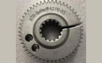
Explore practical KTR BoWex hub guides for engineers, maintenance teams, machinery owners and spare-parts buyers. This technical knowledge section explains how to identify an installed BoWex coupling hub, interpret its markings, count the external teeth, measure the bore or spline and select the correct original replacement component.
KTR BoWex hubs are used with different curved-tooth coupling systems, including BoWex FLE-PA flange couplings, BoWex-ELASTIC elements and selected BoWex sleeve couplings. Although several hubs may appear similar, they can differ by coupling size, external tooth profile, internal spline, bore diameter, keyway, hub length and axial mounting arrangement.
The articles in this category focus on practical identification and inspection questions. Use them to collect the correct technical information before ordering and to avoid selecting a hub that fits the shaft but does not correspond with the installed coupling flange or element.
A KTR BoWex hub is the metal component that connects the coupling with the hydraulic pump shaft, gearbox shaft or another driven component.
Depending on the BoWex coupling design, the hub normally has:
The curved-tooth connection transfers torque while allowing limited axial, radial and angular displacement within the limits specified for the complete coupling system.
The hub must match both sides of the drivetrain: its external teeth must correspond with the coupling element, while its internal connection must correspond with the installed shaft.
Correct identification should begin with the complete description stamped, engraved or printed on the hub.
Use the KTR BoWex hub identification guide to see which markings, measurements and photographs should be collected.
Clean the hub carefully and inspect the complete outer surface, front face and rear face. Dirt, corrosion, grease or the installed position may conceal part of the description.
Look for information such as:
Copy the complete marking exactly as it appears. Do not omit letters, hyphens or suffixes, because they may identify a different hub length, bore or mounting arrangement.
Existing BoWex hubs can carry descriptions such as:
The numerical part commonly helps identify the coupling size, while the letters describe a particular hub or mounting execution.
Do not interpret a partial marking as a complete order code. Two hubs carrying the same nominal BoWex size may still have different:
When the meaning of a suffix is uncertain, compare the hub with the corresponding KTR drawing rather than selecting a replacement from the size alone.
Before requesting a replacement KTR BoWex hub, collect all available information from the existing coupling and the complete machine.
Please provide:
The original hub description or drawing number should be used as the main identification reference whenever it remains available. Measurements, tooth counts and machinery information should provide additional confirmation.
The external curved teeth engage with the internal teeth of the corresponding BoWex coupling flange, elastic element or polyamide sleeve.
When the product marking is unavailable, count the external teeth carefully. Mark the first tooth before counting to avoid including it twice.
Also record:
The external tooth count can help identify the probable coupling size, but it is not always unique. Different BoWex sizes or product families may use similar tooth counts, so the bore, hub length and matching coupling component must also be checked.
A BoWex FLE-PA coupling combines a fibre-reinforced polyamide flange with a steel hub featuring external curved teeth.
The hub and flange must correspond with the same BoWex tooth system. A hub that fits the hydraulic pump shaft can still be incorrect if its external teeth do not match the FLE-PA flange.
Use the KTR BoWex FLE-PA flange identification guide to identify the matching flange size, internal tooth count and outside diameter.
Before combining the components, confirm:
Do not force a hub into a flange when the teeth do not engage smoothly. Resistance can indicate an incorrect size, damaged teeth, contamination or an unsuitable axial position.
KTR BoWex FLE-PA systems are available in several nominal sizes. AWELASTIC currently groups the main original flanges under the following product ranges:
Additional BoWex sizes may be used in particular machinery configurations. The correct hub must be selected from the installed component, original drawing or complete drivetrain specification rather than from this list alone.
BoWex-ELASTIC couplings use a highly flexible circular element with an internally toothed axial connection. The matching BoWex hub is inserted into this internal connection.
Use the KTR BoWex-ELASTIC identification guide to identify the element size, HE execution, flange dimensions and Shore hardness.
The hub must correspond with:
Shore hardness identifies the elastic element, not the steel hub. However, the hub and element must still form the correct matched coupling assembly.
Some KTR BoWex hubs use a finished cylindrical bore for mounting on a standard shaft.
When identifying a cylindrical-bore hub, measure:
Do not measure only the accessible front edge of a worn bore. Take several measurements along the full bore to check for taper, damage or uneven wear.
A keyed hub transfers torque between the shaft and hub through a corresponding shaft key and keyway.
Before ordering a keyed hub, verify:
A hub with the correct bore diameter but an incorrect keyway can be impossible to install or unsuitable for reliable torque transmission.
The replacement should follow the original shaft and key specification rather than being modified without appropriate engineering confirmation.
Many hydraulic pump applications use a splined BoWex hub rather than a plain cylindrical bore.
Internal spline identification requires more than measuring the central opening. Please record:
If some hub teeth are cut away or difficult to count, inspect the matching shaft and compare its complete spline profile.
A hub should not be selected solely from the number of spline teeth. Different spline standards can share the same tooth count while having different diameters, pressure angles or tooth profiles.
KTR also supplies BoWex hubs with taper bores, inch bores and application-specific connections for hydraulic pumps and industrial machinery.
For these hubs, provide:
Do not replace a taper-bore or inch-bore hub with a visually similar metric component without confirming the complete connection specification.
When the hub has no readable marking, identification must be based on its complete physical specification.
Measure and photograph:
Place a ruler or calliper clearly within the photograph, but also provide the measurements separately. Perspective distortion can make dimensions taken from photographs unreliable.
BoWex hubs can be produced with different total lengths and shaft-engagement arrangements.
A short and long hub may share the same external tooth system while differing in:
Selecting the wrong length can result in incomplete tooth engagement, contact with surrounding components or an incorrect engine-to-pump installation distance.
Always measure the existing hub before removal and record its orientation within the coupling assembly.
The hub’s external teeth must engage with the coupling element over the axial length specified for the particular BoWex system.
Insufficient engagement can concentrate the transmitted load over a limited tooth area and accelerate wear. Excessive insertion can cause unwanted contact or prevent correct assembly.
Before operation, verify:
Use the appropriate KTR assembly drawing and instructions for the exact coupling configuration.
Inspect the hub when the machine develops unusual drivetrain noise, increased rotational clearance, vibration or repeated damage to the matching flange or elastic element.
Possible signs of hub wear include:
A new flange or coupling element should not be installed on a severely worn hub.
Hub damage can result from normal wear, but it can also indicate an installation or drivetrain problem.
Possible causes include:
The cause of premature wear should be identified before fitting the replacement part. Otherwise, the new hub, flange or elastic element may fail again.
Do not inspect only the visibly damaged hub. Check the complete connection between the engine and driven equipment.
Inspect:
A worn or incorrectly mounted connected component can damage a new original BoWex hub.
An original KTR BoWex hub is manufactured for the specified tooth profile, dimensions, bore or spline geometry and operating requirements of the corresponding coupling system.
A visually similar replacement may differ in:
These differences can affect fitment, load distribution and the service life of the complete coupling assembly.
When inspecting an existing or replacement hub, look for:
A similar external shape or matching tooth count alone does not confirm that the hub is original or suitable for the installed drivetrain.
KTR BoWex hubs are used in mechanical engineering, hydraulic drives and engine-driven power-transmission systems.
Typical applications can include:
The machine model can help narrow the search, but it does not replace verification of the original hub, coupling and shaft specifications.
Technical documentation can help confirm hub dimensions, coupling sizes, mounting arrangements, tooth engagement and installation requirements.
Visit the KTR BoWex FLE-PA catalogues and assembly instructions page to access available technical information.
Use documentation corresponding with the exact coupling type and size. General BoWex product-family information should not be applied automatically to every hub execution.
Browse the complete KTR coupling catalogue for original BoWex FLE-PA flanges, BoWex-ELASTIC elements, ROTEX spiders, BoWex M sleeves and related components.
For engine-to-pump flange couplings, browse the KTR BoWex FLE-PA product range.
For highly flexible engine-driven applications, browse the original KTR BoWex-ELASTIC elements.
The WooCommerce product categories are intended for comparing and purchasing components, while this post category provides hub identification, measurement and inspection guidance.
Additional AWELASTIC technical resources include:
Each KTR coupling family has its own identification method. A BoWex hub should always be matched with the exact flange, sleeve or elastic element used in the installed assembly.
If the installed hub cannot be identified, send AWELASTIC the complete visible markings, external and internal tooth counts, bore or spline measurements, overall length, machine details and clear photographs.
The articles in this post category provide practical assistance with KTR BoWex hub markings, external tooth identification, spline measurement, flange compatibility, wear inspection and original replacement-hub selection.
Read ArticleRead ArticleDiscussion - Accurately identifying Bowex FLE-PA hubs is essential for ensuring proper...