
Read ArticleRead ArticleDiscussion - Centaflex K couplings are usually clear to specify. A full description of the...
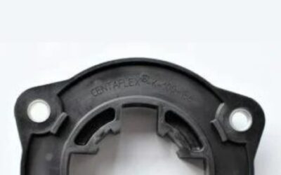
Explore practical CENTAFLEX K coupling guides created for maintenance teams, engineers, equipment owners and spare-parts buyers. This technical knowledge section explains how to identify an installed CENTAFLEX K coupling, determine its size, check the flywheel connection, inspect the matching hub and select the correct original replacement components.
CENTAFLEX K is not identified only by its outside diameter or general appearance. The complete coupling specification can include the nominal size, flange diameter, SAE flywheel standard, hub design, spline dimensions and connection with the installed hydraulic pump or splitter gear.
The articles in this category focus on practical identification, inspection and replacement questions. Use them to collect the correct technical information before ordering and to avoid selecting a visually similar but incompatible flange or hub.
CENTAFLEX K couplings are often relatively straightforward to identify because the full flange description is normally moulded, stamped or otherwise marked on the existing component.
Start with the CENTAFLEX K coupling identification guide to learn which markings, measurements and photographs should be collected before selecting a replacement.
Check the complete circumference and both sides of the flange for information such as:
If the flange marking is damaged or no longer readable, the coupling may need to be identified through its dimensions, flywheel connection, hub design and installed equipment.
Before requesting a replacement CENTAFLEX K flange or hub, collect all available information from the coupling and the complete machine.
Please provide:
The product marking should be used as the primary identification reference whenever it remains readable. Measurements and machine information provide additional confirmation.
The CENTAFLEX K product range represented in the AWELASTIC catalogue includes four principal coupling sizes:
The size affects the coupling dimensions, hub design and permissible drivetrain requirements. A larger numerical size should not be selected simply because it appears stronger. The replacement must correspond with the original engine, flywheel, hub and hydraulic pump configuration.
Browse all available original CENTAFLEX K coupling flanges and elements by size and connection specification.
When the flange marking is damaged, the number of steel jaws on the matching hub can help identify the probable CENTAFLEX K size.
The jaw count is a useful identification indicator, but it does not confirm the complete flange or hub specification by itself. The flywheel size, flange diameter, hub bore and spline connection must still be checked.
CENTAFLEX K 100 is used in compact diesel-hydraulic drive arrangements where a short and torsionally stiff engine-to-pump connection is required.
Available K 100 flanges can have different outside diameters and different SAE flywheel connections. A K 100 designation alone is therefore not sufficient to select the correct component.
When identifying a K 100 coupling, check the complete CF-K marking, flange diameter, bolt pattern, flywheel standard and the four-jaw matching hub.
CENTAFLEX K 125 couplings are used in selected construction, agricultural and mobile hydraulic drive systems requiring a larger engine-to-pump connection.
Available versions include standardised SAE flywheel flanges and application-specific outside diameters. Confirm the complete flange designation and the six-jaw hub before ordering.
Do not assume that two K 125 flanges are interchangeable because their hub connection appears similar. The engine-side mounting geometry can differ significantly.
CENTAFLEX K 150 couplings are intended for higher-load hydrostatic drive arrangements found in heavier construction and industrial equipment.
The K 150 hub can be recognised by its eight steel jaws, but the hub spline and flange connection must still match the installed drivetrain.
Check the complete product marking, outside flange diameter, bolt pattern and flywheel standard before replacing the coupling.
CENTAFLEX K 200 is the largest CENTAFLEX K size currently represented within the AWELASTIC product range. It is used in selected high-load engine-to-pump and heavy machinery applications.
The matching hub normally has twelve steel jaws. However, the exact hub bore, spline and mounting arrangement must be confirmed using the original component or technical drawing.
A K 200 flange should not be selected only from its nominal size or outside appearance. The complete original specification remains essential.
Many CENTAFLEX K flanges are designed for standard SAE flywheel connections. The SAE designation describes the engine-side flywheel dimensions and mounting arrangement.
Common product descriptions can include designations such as SAE 6½, SAE 8, SAE 10, SAE 11½ or SAE 14, depending on the CENTAFLEX K size and flange version.
Before selecting an SAE flange, verify:
Do not identify an SAE flywheel only from one approximate measurement. Compare the complete dimensional pattern with the relevant technical documentation.
Not every CENTAFLEX K coupling uses a standard SAE flywheel connection. Some flanges are identified by a specific outside diameter or application-related designation.
Examples can include product markings in which the nominal K size is followed by a numerical flange diameter rather than an SAE standard.
For non-standard flanges, provide accurate measurements of:
A technical drawing or clear photograph with the measurement points marked can significantly improve identification accuracy.
The coupling hub connects the CENTAFLEX K flange with the hydraulic pump shaft or another driven component. Correct flange identification does not automatically confirm the correct hub.
Hub selection can depend on:
When an original hub number is unavailable, provide a drawing, detailed measurements and clear photographs of the internal spline or bore.
A CENTAFLEX K assembly normally uses a polyamide flange together with a matching steel hub. Both components must correspond with the same coupling size and drivetrain configuration.
A flange of the correct size can still be unsuitable when combined with the wrong hub. Differences in jaw count, spline profile, shaft connection or installed length can prevent assembly or cause incorrect drivetrain operation.
Inspect both components before ordering and determine whether only the flange, only the hub or the complete matched assembly requires replacement.
Original CENTAFLEX K components are manufactured for the specified coupling dimensions, connection geometry and operating characteristics of the corresponding drivetrain.
An unverified alternative may resemble the original flange but differ in polyamide composition, dimensional accuracy, temperature stability, jaw geometry or manufacturing consistency.
These differences can affect fitment, hub engagement and the reliability of the engine-to-pump connection.
When checking a replacement, look for:
A similar colour or outside shape alone does not confirm that a component is technically interchangeable.
Inspect the coupling when the machine develops unusual drivetrain noise, increased vibration, irregular hydraulic operation or visible movement between the engine and hydraulic pump.
Common signs of damage include:
The cause of premature failure should be identified before a new component is installed. Repeated damage can indicate incorrect alignment, worn mountings, a damaged hub, excessive drivetrain movement or an unsuitable replacement part.
Do not inspect only the visibly damaged flange. Check the complete connection between the diesel engine and hydraulic pump or splitter gearbox.
Inspect:
A new flange can fail prematurely when installed with a damaged hub, worn spline, loose pump mounting or incorrect axial position.
CENTAFLEX K couplings have high torsional and radial stiffness and are primarily intended for accurately aligned flange-mounted drive systems.
Small alignment deviations expected in correctly assembled flange-mounted drives can be accommodated, but the coupling should not be used to correct major installation errors or unsuitable engine-to-pump geometry.
During installation:
Installation procedures and tightening values should follow the relevant manufacturer documentation for the specific coupling and machine.
CENTAFLEX K couplings are commonly used in diesel-driven hydrostatic systems and other compact engine-to-pump connections.
Typical applications include:
The machine model can help narrow the search, but it should not replace the original coupling code. Equipment from the same model range can use different engines, hydraulic pumps, flywheels or hub specifications.
Technical documentation can help confirm coupling sizes, flange dimensions, torque ratings, permissible speeds, flywheel connections and installation requirements.
Visit the CENTAFLEX K catalogues and technical downloads page to review available specifications and dimensional information.
Technical data should always be evaluated together with the original engine, hydraulic pump and machine configuration. Selecting a coupling only by nominal torque or outside diameter can overlook critical mounting details.
Browse the complete range of original CENTAFLEX K flanges and coupling components by nominal size, flange diameter and SAE flywheel connection.
Individual product pages provide product codes, photographs, dimensions, current availability and delivery information.
You can also return to the main CENTAFLEX coupling guides category for information about CENTAFLEX A, H, K and X coupling systems.
If the required CENTAFLEX K flange or hub cannot be identified, send AWELASTIC all visible product markings, flange and hub measurements, equipment details and clear photographs.
The articles in this category provide practical help with CENTAFLEX K identification, size comparison, SAE flywheel selection, hub inspection, original-part verification and correct replacement component selection.
Read ArticleRead ArticleDiscussion - Centaflex K couplings are usually clear to specify. A full description of the...